Company profileChairman’s StatementQualificationsBranchesContact Us

honesty, respect, cooperation, creativeness’
Enterprise NewsIndustry dynamics
Supplier of comprehensive power system and electrical energy saving solutions
Smart GridElectrical Energy SavingRenewable EnergyElectrical engineering
Supplier of comprehensive power system and electrical energy saving solutions
Service TenetService CommitmentService NetworkService HotlineDialogue with experts in QQ
Supplier of comprehensive power system and electrical energy saving solutions
We have set offices in more than ten cities in China to support our business all over the country, as well as an Overseas Business Department.
Enterprise recruitmentcampus recruitmentnetwork recruitmentHuman Resource Strategy
Supplier of comprehensive power system and electrical energy saving solutions

010-89480705
a89480710@163.com
No 9, Linhe Street, Shunyi District, Beijing, China
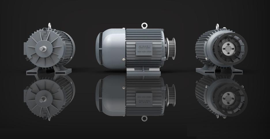
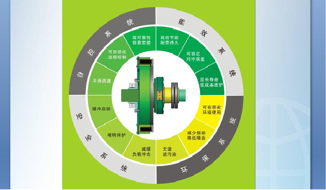
Permanent Magnetic Speed Control and Permanent Magnetic Coupling Technology:
Energy efficient motors using frequency conversion and speed control technique or permanent magnet drive technique (permanent magnetic speed control and permanent magnetic coupling technology) are always chosen to save energy. Though HV motors generally uses high voltage frequency conversion and speed control technique for energy saving, such motors usually have disadvantages of generating harmonics, being damage-prone, high operation and maintenance cost, high energy consumption, and relatively short service life, thus will surely be replaced by new devices with more energy efficient technique – the permanent magnetic speed control and permanent magnetic coupling technology. Permanent magnetic coupler: coupler conductor rotor is connected to the motor end, and coupler permanent magnet rotor is connected to the load end. There is no mechanical connection in between. When the motor rotates, the torque produced is transmitted to the load by electromagnetic induction, and the load is driven to work. Permanent magnet speed controller: with torque transmission principle same as that of coupler, it is formed by adding a speed regulating device based on a coupler. Thus it can regulate the effective coupling area of the conductor and the permanent magnet, and change the torque transmitted in between. Adjustable and controllable torque output makes load speed regulating and energy saving possible. Permanent magnetic drive technology can be widely used for motor energy saving in industries such as electric power, metallurgy, coal, petroleum, petrochemical, building materials and so on.
The Working Principle of Permanent Magnetic Speed Regulating Technology:
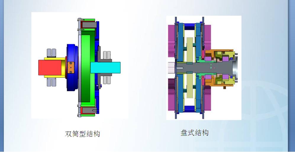
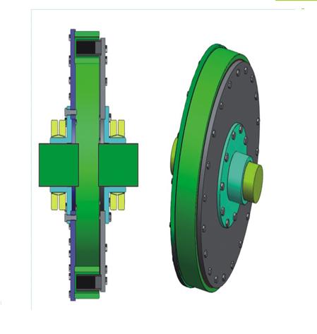
The permanent magnetic speed governor is composed of three parts: the conductor rotor, the permanent magnet rotor and the regulator. Permanent magnetic rotor is inside the rotor conductor. They are parted by air gap, and rotate independently with the rotating shafts on which they are respectively installed. Regulator adjusts the relative position between permanent magnetic rotor and conductor rotor in the horizontal axial direction, so as to change the interaction area between conductor rotor and permanent magnet rotor, and the magnitude of torque transmission between conductor rotor and permanent magnet rotor. Conductor rotor is installed on the input shaft, and permanent magnet rotor is mounted on the output shaft. When the conductor rotor rotates, conductor rotor and the permanent magnet rotor produce relative motion; eddy currents are generated on the conductor rotor by the permanent magnetic field; in the meantime, eddy currents produce an inducted magnetic field which interacts with the permanent magnetic field, thus driving the permanent magnet rotor to rotate in the same direction as the conductor rotor does, as a result, the torque of the input shaft is transferred to the output shaft. The magnitude of the output torque is associated with the area of the interaction, the greater the interaction area, the greater the out torque, and vice versa. When the permanent magnet rotor moves along the axial direction, the area of interaction between the permanent magnet rotor and the conductor rotor is changed. The larger the interaction, the higher the transmitted torque, and the higher the rotation speed; the smaller the smaller the interaction, the lower the transmitted torque, the lower the rotation speed. When the interaction area between permanent magnet rotor and conductor rotor becomes zero, the rotation speed of the permanent magnet rotor is zero, i.e. load rotating speed is zero.
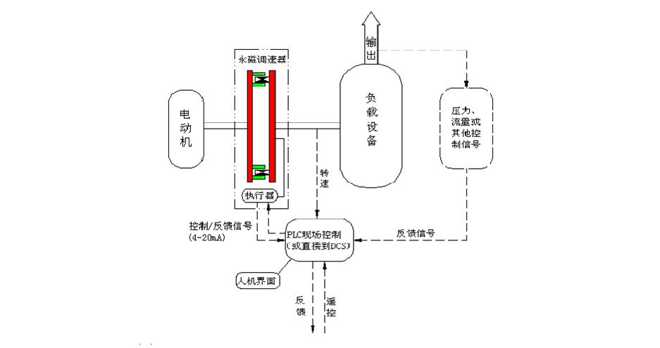
The electric actuator provides power for the speed regulating mechanism, adjusts the coupling area as well as the torque output according to the instructions given by the control center, and sends feedback to the control center.
Control center can be PLC control, intelligent instrument control, or DCS control.
Control signal source are in fact the control objects required by specific technical needs. For pump system, the control objects may be pipe pressure, flow, or liquid level; while for fan system, the control objects may be technical parameters like pressure, flow etc. Therefore, the control signal source may be pressure, flow, liquid level and other parameters, which could be converted to 4 ~ 20mA of the current signal by transmitter to instruct electric actuator to act.
The permanent magnetic speed controller realizes the non-contact connection between the motor and the load, and effectively solves the problems of rotating load system on the middle and the soft start, speed regulation and energy saving, vibration reduction, etc.

Energy-saving principle of permanent magnet speed adjustment technology:
Permanent magnet speed adjustment technology can be used to realize continuous control of flow and / or pressure by adjusting the air gap, and to replace the valve or damper for flow and / or pressure control in original system. Therefore, speed of the wind generator or pump can be replaced in condition of constant motor rotation speed.
Permanent magnetic transmission technology is mainly about transmitting torque: motor output torque = load torque required.
The working characteristics of permanent magnetic speed governor suit best for centrifugal loads such as wind generator and water pump.
Fan and water pump using baffle and valve to regulate the flow will lead to increase in air resistance and water resistance, thus causing energy loss; while changing flow through adjusting the wind generator and pump speed will cause no increase in air or water resistance, thus avoiding energy loss;
According to working principle similar to that of fluid machinery, i.e. the flow is proportional to load torque; power is proportional to the cube of rotation speed. Therefore, the energy saving effect is remarkable.
扫一扫
,
关注我们


